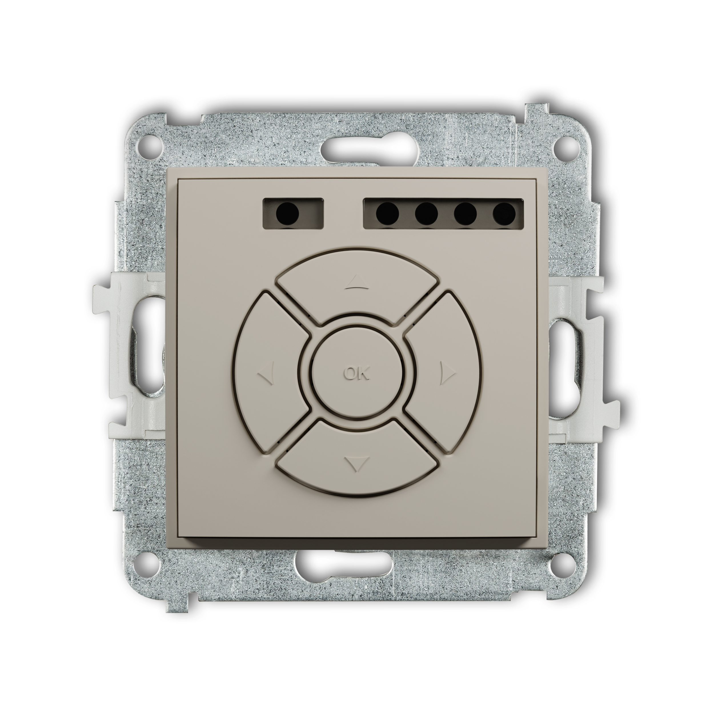
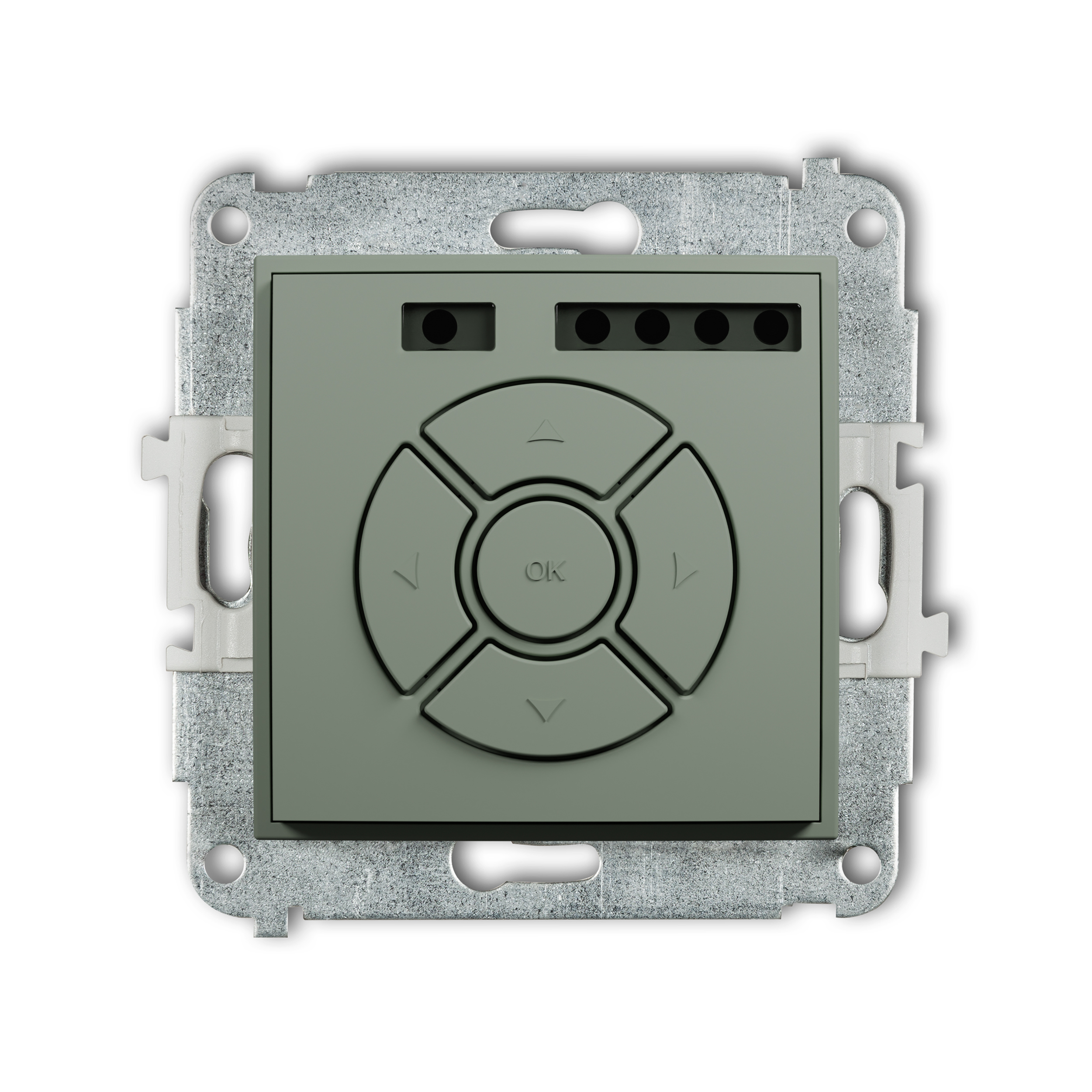
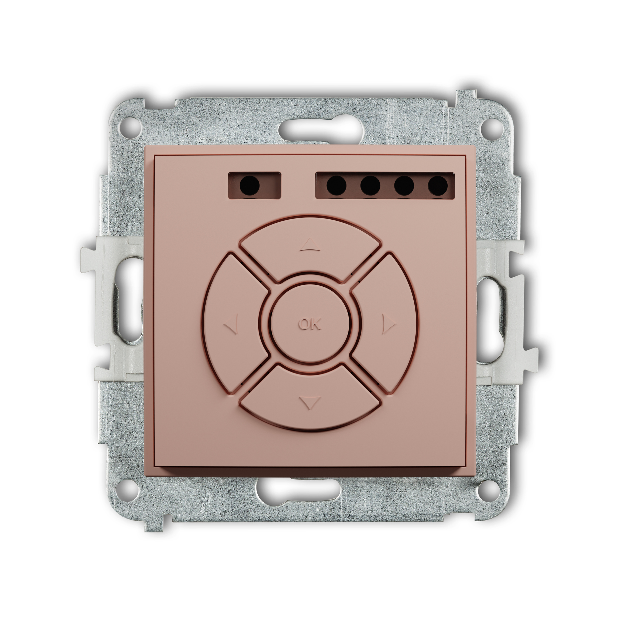
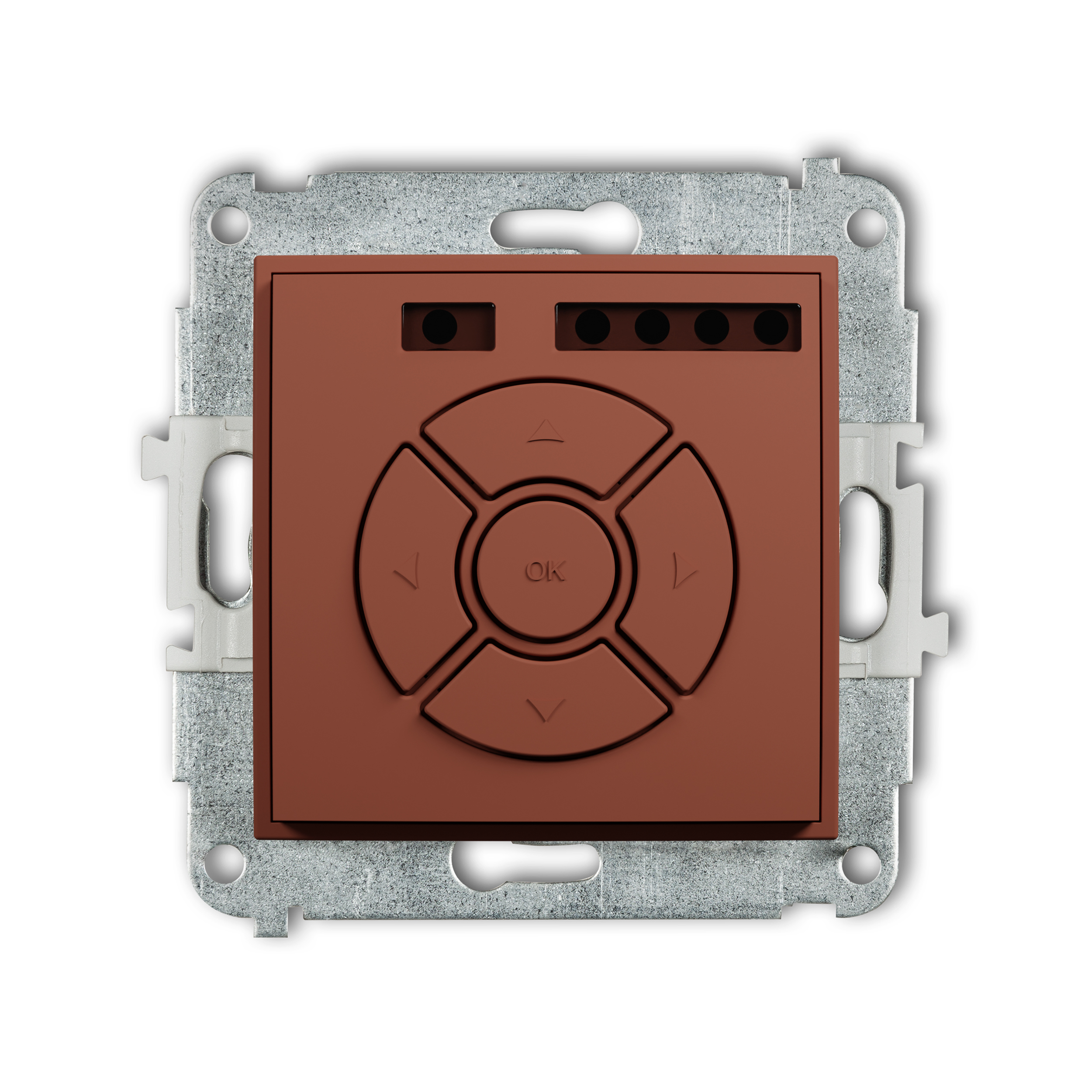
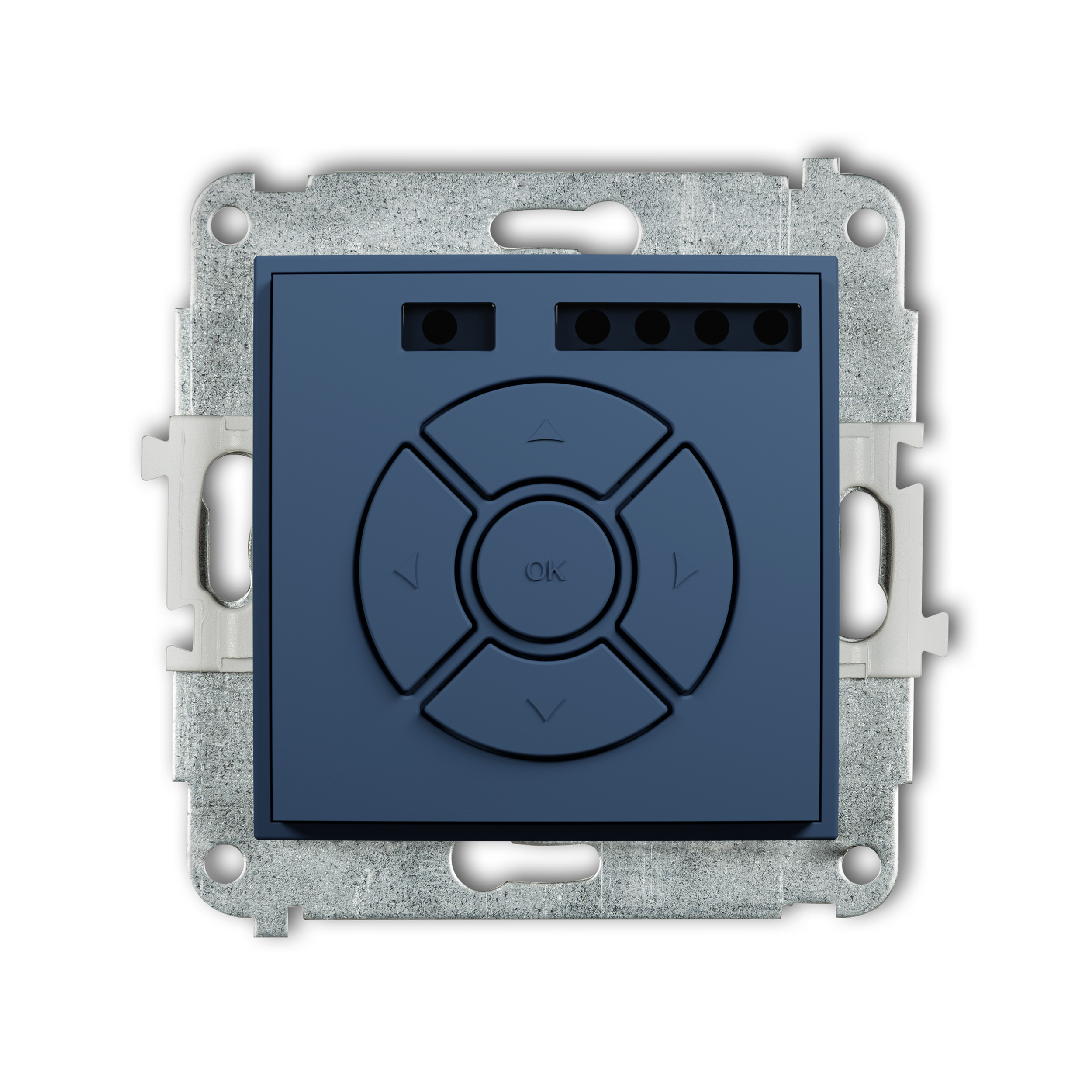
Electronic control roller shutter mechanism (local control)

white
ISR-1
Product description
Downloads
ICON mechanisms and frames are sold separately.
The device is designed for controlling roller blinds equipped with electric motor with power up to maximum 150W, 230V 50Hz electric mains-operated.
Note! one controller operates locally only one blind.
More information in the DOWNLOADS section.
The actual appearance of product may be different from the presented photographs.
Technical data
| Protection index | IP 20 |
| Power supply | 230 V~ 50 Hz |
| Load range | max 150 W |
| Type of load | Inductive – single phase motor 230 V~ 50 Hz |
| Type of work | Intermittent |
| Cross-section of power supply cords | 0,75 ... 1,5 mm2 |
| Cross-section of control cords for BUS line | 3 x 0,5 ... 1 mm2 |
| UV resistance | Resistant |
Product variants
-

Electronic control roller shutter mechanism (local control and remote control)
white
ISR-2
-

Electronic control roller shutter mechanism (central/additional button)
matt black
12ISR-6
-

Electronic control roller shutter mechnism (local control, remote control, zone control, central/additional button)
matt grey
27ISR-3A
-

Electronic control roller shutter mechanism (local control and remote control)
matt graphite
28ISR-2
-
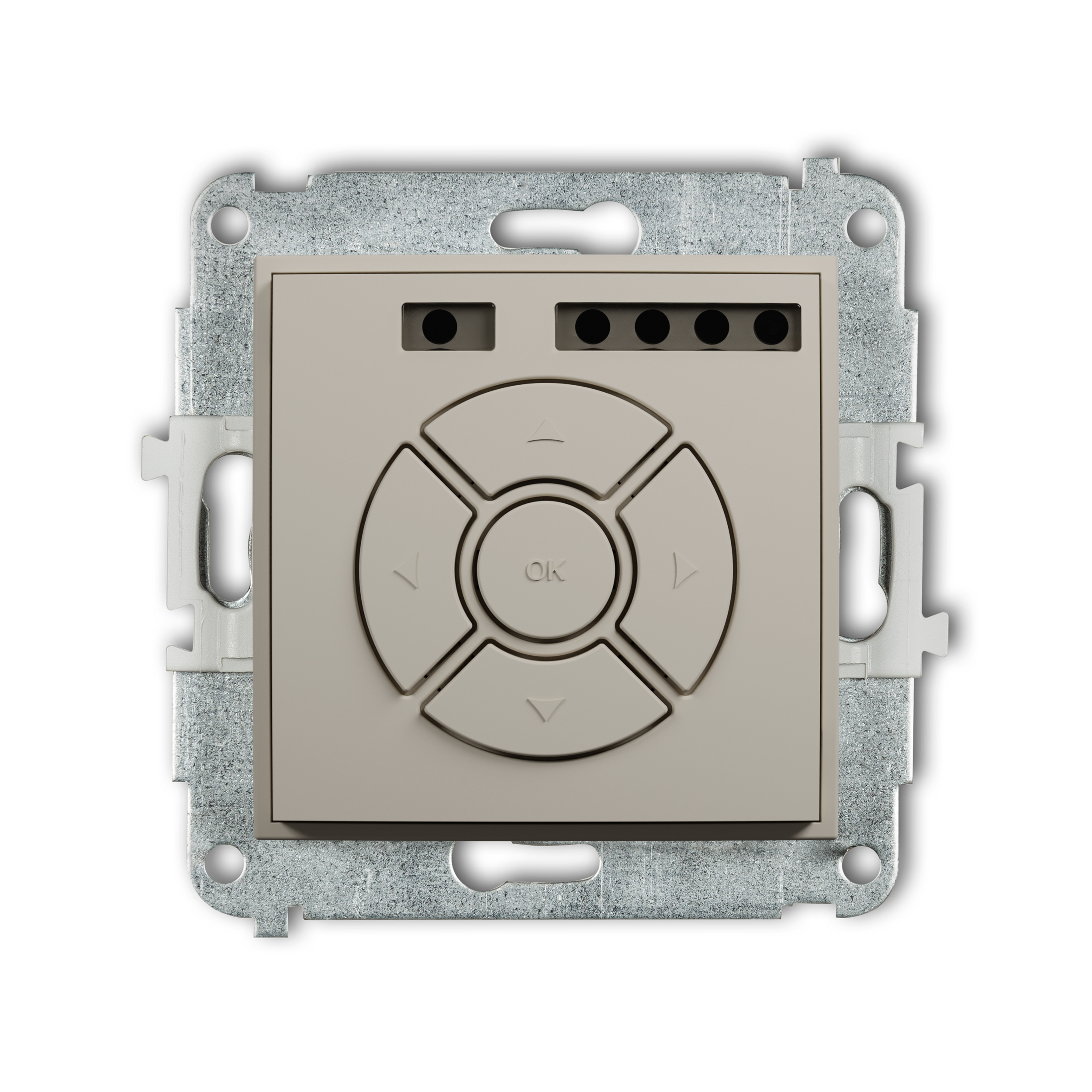
Electronic control roller shutter (local control, remote control, zone control)
taupe
60ISR-3
-
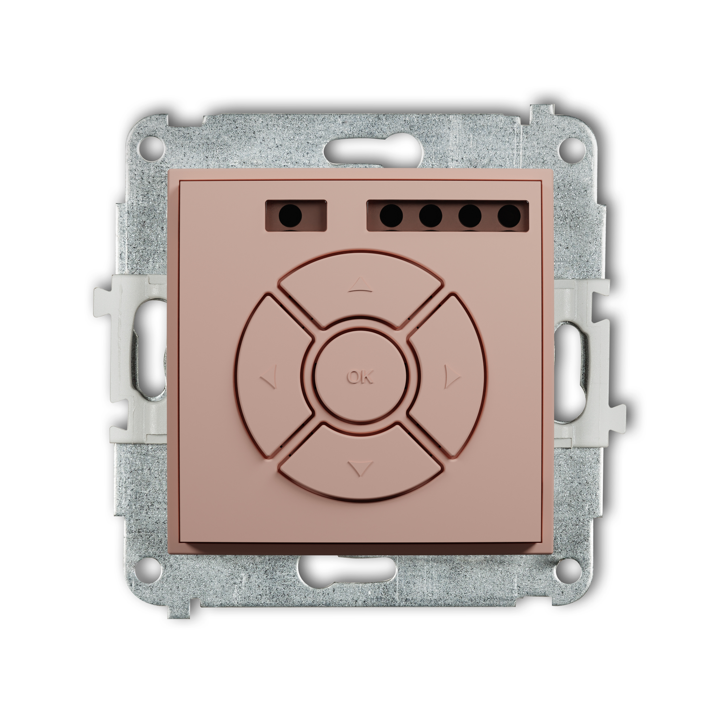
Electronic control roller shutter mechanism (zone button function)
salmon
62ISR-5
Complementary products
Related products
-

Single push button "light" mechanism
white
IWP-5
-

Splash proof socket with the 2P+Z earth mechanism (shaded transparent cover, with increased contact protection/shutter)
matt black
12IGPB-1zdp
-

BNC single socket mechanism
matt grey
27IGBNC-1
-

Single push button "light" mechanism
matt graphite
28IWP-5
-
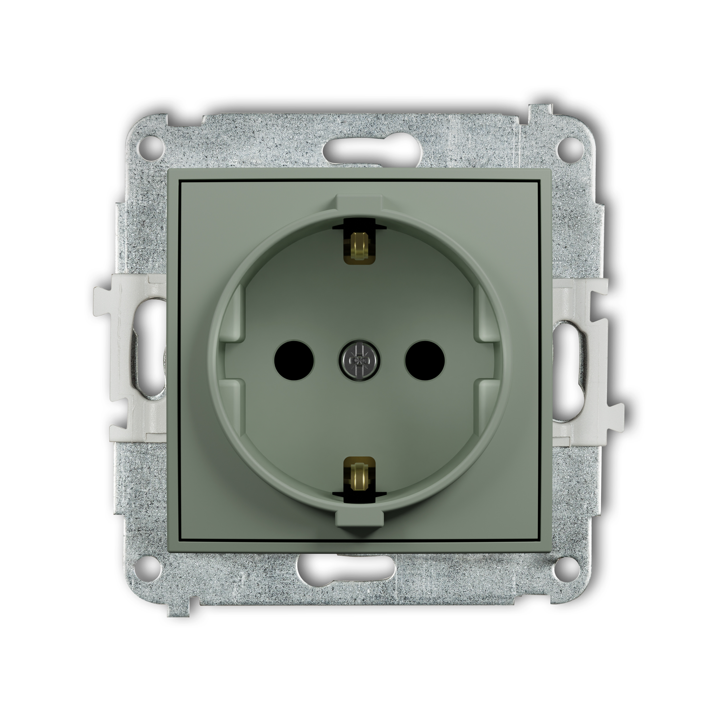
Single socket with the 2P+Z earth SCHUKO mechanism (child protection)
sage
61IGP-1sp
-
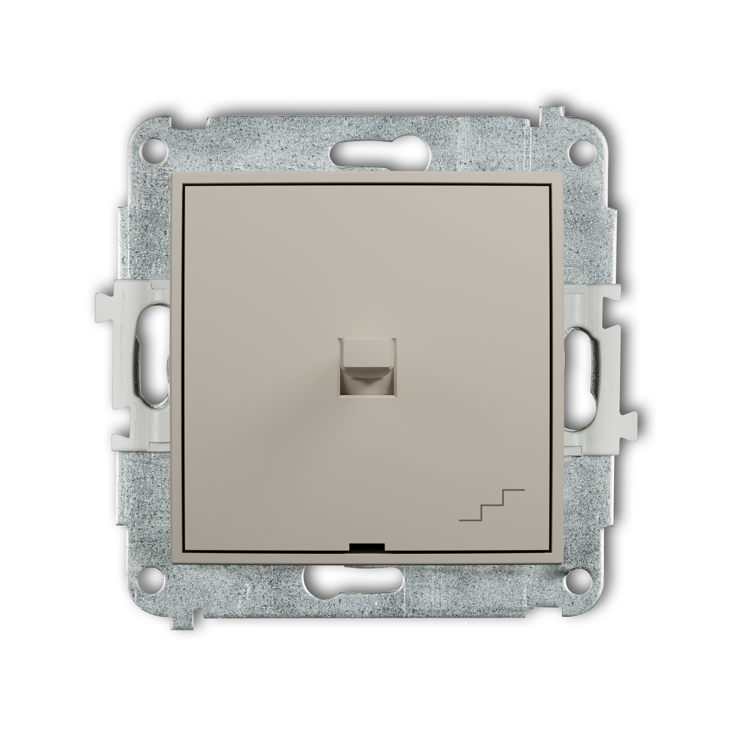
American-style two-way switch mechanism
taupe
60IWPUS-3
3D MODELS
INSTRUCTIONS
-
Assembly manudal of RTV and RTV-SAT outlet sockets _ ICON
-
Assemlby manual computer sockets 5e, 6_ ICON
-
Assemlby manual computer sockets 6a, 7, 8 _ ICON
-
Assembly manudal illuminating module LED for switches _ ICON
-
Assembly manual sealent (IP44) to switches _ ICON
-
USB charger USB A assembly and connection instruction_ICON
-
USB charger USB A without description field assembly and connection instruction_ICON
-
Doble USB charger 2xUSB A assembly and connection instruction_ICON
-
Doble USB charger 2xUSB A without description field assembly and connection instruction_ICON
-
Doble USB charger 2xUSB C assembly and connection instruction_ICON
-
Doble USB charger 2xUSB C without description field assembly and connection instruction_ICON
-
Doble USB charger USB C + USB A assembly and connection instruction _ICON
-
Doble USB charger USB C + USB A without description field assembly and connection instruction _ICON
-
User manual electronic temperature controller with underfloor sensor _ ICON
-
User manual electronic temperature controller with aerial sensor _ ICON
-
User manual universal electronic week temperature controller _ ICON
-
User manual electronic lighting controller with push and rotary button _ ICON
-
User manual electronic lighting controller with push and rotary button for LED lamps _ ICON
-
User manual electronic lighting controller with push and rotary button for use 1-10 V voltage controlled power supply unit _ ICON
-
User manual electronic motion detector _ ICON
-
User manual electronic roller blinds _ ICON

